Power Electronics, Machines and Drives
Recent Research Topics include:
- Drives (SR Motor, Induction Motor, PMSM/ BLDC motors etc.)/Photo-Voltaics/FACTS applications/Electric Vehicle/Multi-level Inverters etc.)
- Space vector Pulse Width Modulated Inverter Controlled Induction Motor drive
- Linear Induction Motor Drives
- FACTS devices and speed control of switched reluctance motor using DSPs
- Matrix converters
- Induction heating
- Attraction & Repulsion type levitation
- Welding applications
- Study on Nonlinear Phenomena in Power Electronic and Drives
National Mission in Power Electronics Technology(NaMPET) project – Phase I & II
The Department was selected primarily for Power Electronics Infrastructure up-gradation activities in November 2004 under the NaMPET project launched by the DIT, MCIT, Govt. of India. A state-of-the-art facility has been created in the form of the Advanced Power Electronics Laboratory. The Department also participated in a networked Research Project entitled “Development and validation of SEQUEL and Real time model of various electric drives”(FSS-Project), held the first NWPE in 2005 under the aegis of NaMPET and two Short term courses on Power Electronics in July, 2009 and January 2010. A team of faculty members have been pursuing teaching and research activity for more than a decade now. Regular seminars by experts in PE in the form of IEEE seminars, industry inter-action in the way of regular visits and discussions with different industry/consulting companies, consultancy and industrial R&D activity with organisations like Webel Mediatronics, Webel Tools India, Naskar & Co., Electrotherm India, Liveline Electronics, GE Motors etc. have become a part and parcel of the activity apart from teaching and funded research with support from different GoI funding agencies. This slowly led to emergence of the Advanced Power Electronics laboratory (APE lab) as a regional centre of excellence in the area of Power Electronics.
Advanced Power Electronics Laboratory:
Ongoing Research work:
Design, fabrication , analytical and experimental Investigations on Permanent Magnet Synchronous Machines for Different Applications in the Power Range of 2-5 kW
A 2kW PMSG has been fabricated in the laboratory. The developed set-up has been coupled with a dc motor. A back to back PWM converter is fabricated. A laboratory scale dc-dc converter (Ćuk converter is proposed here) which will be used as an extra power electronic converter to increase the operating range of the generator has been fabricated and control strategy has been implemented. The following figure shows the configuration of the total system.
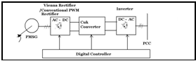
Schematic Diagram
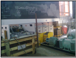
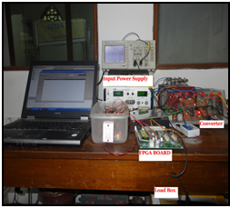
Total Setup
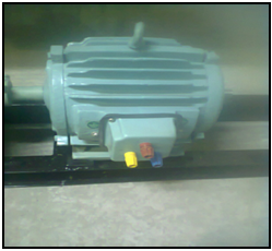
PMSG
Ćuk converter
This work is expected to develop a new technology for controlled operation of an energy conversion unit in the power range of 2-5 kVA and suitable for pico-hydel system in remote hilly region where there are sources of fast flowing mountain streams but no electricity as transmission of electricity from national grid is not possible due to the distance and remoteness of those places.
Design, Fabrication of BLDC motor and implementation of closed loop control techniques
A 0.75 hp, 400 Vdc , 1500 rpm , 4 pole, 3-phase surface mounted PM -BLDC has been designed and fabricated. It is designed to be fed from 1-phase 230V, 50 hz ac supply. For the present work the magnets, are being procured at very high costs from the only major source that is China. The motor is intended to be run on a closed loop drive system.
The drive system consists of two back to back connected inverter unit. The 1-phase unit is used for active front end to make the grid side current at UPF with grid voltage and 3-phase unit is used to drive the BLDC motor.
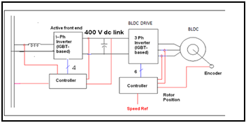
Schematic Diagram
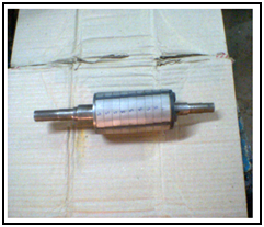
Rotor of BLDC with sleeve
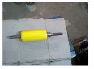
Rotor of BLDC with sleeve
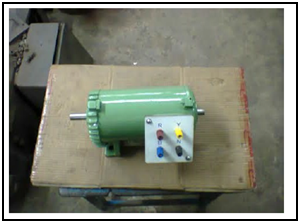
BLDC motor
Design, analysis, fabrication of PMSM and PMSM based variable speed drive
PMSM under load test
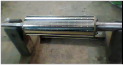
Rotor of PMSM
The work consists of design and fabrication of a 8 pole, 750 rpm, 5 kW PMSM. Fabrication of the machine has been done with the help of local manufacturer. The magnets mounted on the rotor are imported from China. Then the controller for this PMSM for vector control operation will be implemented using FPGA. This vector controlled PMSM will be connected to grid by an Active Front End rectifier, so that the current drawn from grid will be in phase with the corresponding phase voltage i.e. the unity power factor operation.
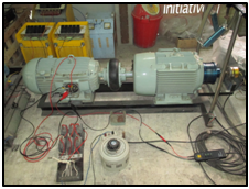
Doubly fed IM drive using SRIM 5kW, 4 pole, 1500 rpm
The work consists of implementation of rotor side control of induction machine. Implementation of slip power recovery is done in the setup. Implementation of FOC in stator and rotor fields is in progress using FPGA platform. The setup will be connected to grid by an Active Front End rectifier, so that the current drawn from grid will be in phase with the corresponding phase voltage i.e. the unity power factor operation. The work is moving towards four quadrant operation of doubly fed IM drive.
Electromagnetic Levitation
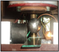
An electromagnetic levitation setup has been designed, modeled and fabricated where a ball of 62 gm mass has been successfully and steadily levitated.
(A)
(B)
(A) An attraction type electromagnetic levitation prototype (extended object) with multi-axis control has been designed, modeled, fabricated.
(B) An attraction type electromagnetic levitation prototype (extended object) with single-axis control has been designed, modeled, fabricated.
Research work Completed:
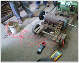
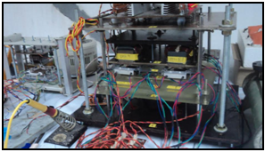
Study on double sided axial flux switched reluctance motor and its application as a direct wheel drive
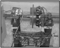
Total Setup
8 stator poles, 6 rotor poles, 24 V, 0.75 HP, 1100rpm DSAF-SRM is shown in the figure. Power electronic converter has been designed and fabricated in the laboratory to drive the motor.
Power Electronic converter for Wielding application
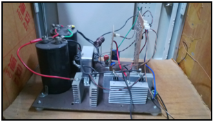
2.2 kW wielding converter has been designed, analysed and fabricated. Switching frequency of switching devices is 50 kHz. Closed loop control has been implemented on this PEC. Zero-Voltage-Switching has been implemented on each power electronic switching device to minimize on state switching loss.
IGBT based 3-phase Interleaved DC-DC Boost Converter fed Multi-level Inverter
Both DSP (TMS320LF2407A) and FPGA(EP1C12Q240C8) are used as hybrid controller. Interleaved converter run from DSP controller and multilevel inverter run from FPGA controller.
Repulsion type Magnetic Levitation
PEC fed IM Drives- Fault detection in IM drives
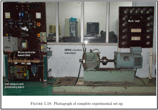
Research Activities are going on in other diverse areas and among them a few are shown here.
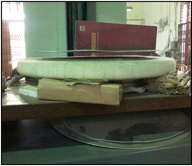
Analysis and Development of a Single-Axis controlled Repulsive-Type Magnetic Bearing,
DST (SERB) Sponsored Research Project:

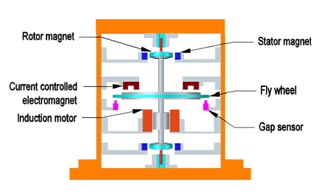
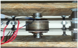
Magnetic Bearing system under fabrication

v/f CONTROLLER VERTICAL SHAFT MAGNETIC BEARING
Ms. Xiaomin Lu, a doctoral student at the Centre for Hybrid Automotive Research and Green Energy (CHARGE), University of Windsor, Canada, visited the Department of Electrical Engineering, IIEST Shibpur to continue portions of her doctoral research under the supervision of Dr. Kaushik Mukherjee during December 2013 and January 2014. This work laid the foundation for the paper entitled, “Investigation of Permanent Magnet Motor Drives Incorporating Damper Bars for Electrified Vehicles”, by “Xiaomin Lu, K.L.V. Iyer, Kaushik Mukherjee, K. Ramkumar and N. C. Kar, published in the IEEE Transactions on Industrial Electronics, vol. 62, no. 5, May 2015, pp. 3234-3244 (DOI 10.1109/TIE.2014.2367023).
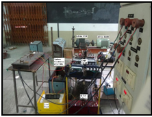
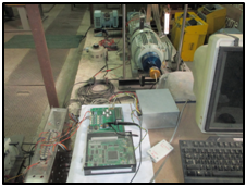
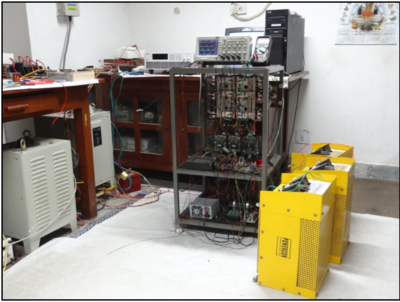
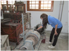
Machines Laboratory of EE Dept., IIEST Shibpur
Power Electronics laboratory of EE Dept.
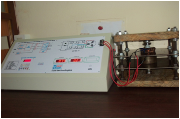
Design of a True RMS Voltmeter:
The fundamental aim of this project was to develop a true-RMS voltmeter, by utilizing a general purpose 8-bit microcontroller. A photograph of the set-up is shown in Fig. 1. The set up gave acceptable results for sine, square and triangular waves. The values, displayed by the set-up, were compared with an industrial true-RMS voltmeter and were found to be matching.
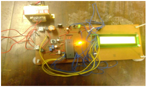
Fig. 1. A snapshot of the hardware set-up for True RMS Voltemeter
Switched Reluctance Machine Drive and Its Applications:
The scheme was tested in real-time simulation, using an FPGA platform and then implemented using analogue / discrete IC based hardware. The whole scheme was tested successfully on an available SRM in the laboratory.
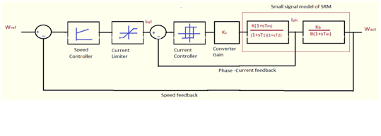
The block diagram of the closed loop control scheme for the SRM
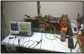
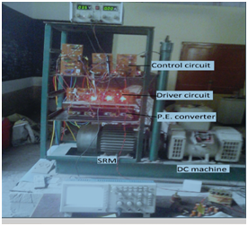
Laboratory-based hardware set up at the Advanced Power Electronics Lab
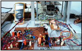
DSP based Dual Converter and Rectifier:
A DSP based dual converter was developed to achieve bi-directional speed control of a separately excited dc motor. The entire control-algorithm was embedded into a DSP, using a code and the closed-loop scheme was tested in hardware. The controller also had features like soft start, smooth speed reversal, intelligent triggering to ensure successful operation at all load conditions.
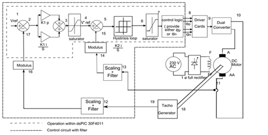
The closed loop control scheme for the dual converter
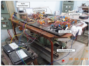
Laboratory set-up for the dual-converter based dc drive